Cisco ACI – Policy Driven Architecture
Making sense of the Cisco ACI policy model

Many people express frustrations with the Cisco ACI object model, so I thought I would write an article on the policy object model and link all the constructs together.
Fabric and Tenant Policies
Coming from traditional networking to working on a Cisco Application Centric Infrastructure (ACI), one of the most confusing changes is the ACI policy-driven model and how all the objects stitch together. So, this article/post attempts to simplify and build on a structure that I’ve used a few times before, linking all the ACI policies together.
Cisco has a lengthy technical reference on the topic: Cisco ACI Policy Model Guide. The ACI policy model manages the entire fabric, including the infrastructure, authentication, security, services, applications, and diagnostics. So, it's quite a change in the way you think.
But the object model is not simply defined, nor does it show how it is stitched together in an easy-to-read way. At its core, it uses a hierarchical, object-oriented structure managed by the ACI central controller (The APIC).
Cisco ACI is hierarchically built of various policy constructs, defined into the two main categories as follows:
- The Fabric Physical Access Policies that define the physical elements of the ACI fabric, such as the switch and interface policies.
- The Tenant Logical Model that defines logical constructs, such as application profiles and EPGs.
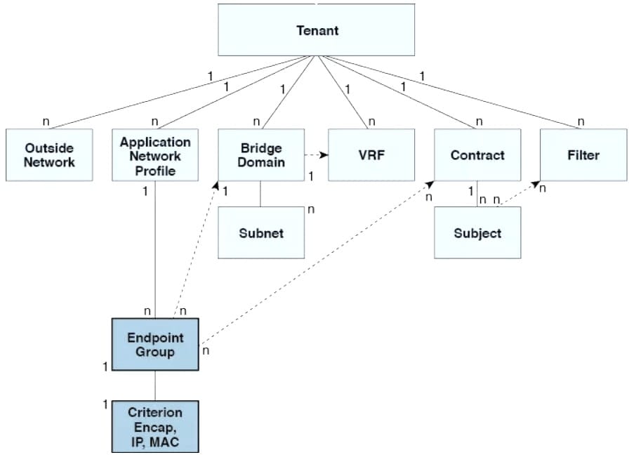
These policy constructs and how they interoperate are shown in the figure below and can be found under the “Tenants” and “Fabric” tabs within the ACI graphical user interface (GUI), respectively.
The above object diagram is one of the better visual representations I've seen, showing how the objects link to one another. Thanks to Brian McGahan (INE.com)
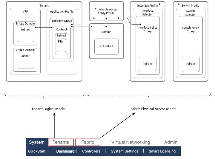
The order of deployment doesn't matter too much, as long as they call on the correct policy construct and link together as shown in the above diagram, packets will flow through the ACI fabric. However, it is sensible to configure them in a specific order, starting with the Fabric Access Policies, as shown in the figure below. This will make linking the various objects a lot easier
Fabric Physical Access Policies
Configuration starting with the Fabric Access policies, and then Tenant Polices is a logical order, as shown in the image below

The description of each of these policies is expanded below:
- VLAN Pools: A VLAN pool specifies the VLAN IDs or ranges used for VLAN encapsulation, enabling traffic to be matched to an Endpoint Group (EPG). VLAN Pools are not the same as the traditional layer 2 VLANs; they do not represent a layer 2 switching domain. Instead, it is a packet tag, or encapsulation, that the ACI uses to classify traffic into an EPG. The two types of VLAN pools are:
- Dynamic Pools: Which are managed via the APIC, and generally used for VMM integration, and
- Static pools: They are generally used for static hosts and endpoints that will be manually configured in the fabric.
- DOMAIN: A domain defines the scope of VLANs. EPGs are then configured to use the VLANs associated with a domain. There are multiple domain types: Physical, Virtual (VMM Domains), External layer 2 and external layer 3. It is common practice to have a one-to-one mapping with a VLAN pool to a Domain, and a separate VLAN Pool and Domain per tenant.
- Attachable Access Entity Profile (AAEP): The Attachable Access Entity Profile (AAEP) is used to map domains (physical or virtual) to interface policies, ultimately mapping VLANs to interfaces. This can be thought of as mapping the fabric access constructs to the tenant constructs. AAEPs are often considered the “glue” between physical access policies and tenant logical constructs. The AEP specifies the range of permitted VLANs but does not configure them. No traffic flows unless an EPG is deployed on the port. Without defining a VLAN pool in an AEP, a VLAN is not enabled on the leaf port, even if an EPG is provisioned. Furthermore, AAEPs allow a one-to-many relationship (if desired) between interface policy groups and domains. With the DCBR design, we have decided on a one-to-many (AAEP-to-Domain) mapping to simplify interface policy groups and reduce the number of configuration changes required for the interface selector
- Interface Polices: Interface access policies enable configuring various functions for spine or leaf switch access interface ports, such as spanning tree, LACP, LLDP, and CDP
- Interface Policy Groups: Interface Policy Groups are templates used to define port behaviour. Interface policy groups utilise the interface policies described above. The type of interface policy groups will influence their use within the ACI Fabric. There are three types of interface policy groups depending on link type:
- Access Ports (individual)
- Port Channel
- Virtual Port Channel (vPC)
- Interface Profile and Interface Selectors: Interface profiles contain blocks of ports and interface selectors and are also tied to the interface policy groups. The table below lists the interface profile names to be configured, and each profile will be configured with all available interface selectors
- Switch Profiles and Switch Selectors: Switch profiles allow selecting one or more leaf switches and associating interface profiles to configure the ports on those nodes
Tenant Logical Model
The second half of the model, the tenant section, is probably where you will spend most of your time, if you're lucky enough to operate this system. A single tenant is the highest-level logical container within the Tenant Logical model. It serves as a secure, isolated boundary for administration, network configurations, and security policies. It includes the following tenant constructs/Polices:
- Virtual Routing and Forwarding (VRF)s information;
- Bridge Domains (BDs), with associated IP Addressing information;
- Application Profiles and EPGs
- Contract and Security information.
- EPGs deployed on a port, PC, or VPC (through static bindings) and;
- External Layer 3 Out information.
These defined constructs will connect to the physical Access policies via the Domain and AAEP, as described above. The diagram below presents the relationship between the tenant policies.
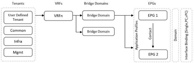
The following explains the various ACI logical constructs as shown in the above figure:
Tenant
- Tenant is the highest-level logical container within the fabric's policy model. It acts as a secure, isolated boundary for administration, network configurations, and security policies. It contains all the tenant constructs. There are three (3) default tenants configured, as described below:
- Common: A tenant designed to provide shared services. Policies, VRFs, and Bridge Domains created in the common tenant can be accessed by all other user-defined tenants. This is highly useful for shared resources such as DNS servers, DHCP servers, or Active Directory. It is common design practice to leverage resources configured in the common tenant and shared to various user tenants. For example, the VRF and BD will be configured in the common tenant, and user-defined EPGs will be configured in the user-defined tenants that point to the common BDs. This provides a way to secure endpoints for a basic multi-tenancy environment. Also, I’ve seen an externally routed environment (L3Outs) configured within the common tenants and shared with the other tenants via a form of route leaking.
- Infra: This tenant handles the internal operation of the ACI fabric itself. It manages the underlying VXLAN overlay, multicast configurations, and leaf- and spine-switch discovery.
- mgmt: Used exclusively for managing the fabric. It contains the policies for in-band and out-of-band management access to the physical switches and the APIC controllers.
- User Defined: Are the main tenants that are created for a company, such as CompanyX_tenant. I often see these broken down by environment (Production, Dev, and DMZ). I prefer creating tenants per environment because it isolates constructs within the container. For example, you probably wouldn’t want to see development or DMZ constructs within a production tenant, as it also exposes user error.
VRF
As with traditional networking, a VRF is a private Layer 3 network or context that provides Layer 3 isolation and a secure boundary to align security zoning requirements. There is a one-to-many relationship with the tenants.
Bridge Domain
A bridge domain (BD) is a Layer 2 forwarding construct within the fabric and a container for Layer 3 information, similar to a Switch Virtual Interface (SVI) in a traditional network. There are two (2) types of BDs defined as follows:
- A layer 2 only BD.
- A layer 3 BD with a configured IP Address to act as a layer 3 gateway for connected endpoints.
If the BD is configured as a “layer 2” only BD for migration activities and the gateway resides outside the ACI fabric, it is important to enable “flooding” for the layer 2 BD to allow endpoints to ARP to the gateway outside the fabric.
Application Profiles
An Application Profile (AP) is a logical container for multiple EPGs, typically related to an application's function.
Endpoint Groups
An EPG is an ACI object that contains a collection of endpoints, usually sharing a common function. The most common way to classify applications or devices into an EPG is via VLAN encapsulation. The whole application-centric system is based on these EPGs, the grouping of applications, and how they talk to each other.
All endpoints and systems within an EPG can communicate freely with each other, but can not talk to an endpoint within another EPG. To allow this communication, a contract is required, which is a type of stateless Access Control List (ACL). The contract is provided by one resource and consumed by another to enable communication.